
بيت /p id symbols legend

Category:PID symbols. From Wikimedia Commons, the free media repository. Jump to navigation Jump to search. Subcategories. This category has the following 9 subcategories, out of 9 total. P PID symbols of columns (10 F) PID symbols of cooling towers (2 F)
الحصول على السعر
>BUY NOW >>REQUEST QUOTATION. Instrumentation Symbols PRO is a graphic instrumentation symbols software developed for Autodesk's AutoCAD, Microsoft's Visio for Windows 7 and 8 ZWsoft's ZWCAD for Windows 7 and Windows 10, and Dassault Systemes' DraftSight ISA instrumentation symbols provide the user with graphic symbols to be used during the engineering .
الحصول على السعر
symbols exist in the various norms they are only particularly suited to the relevant area of application of the norm ( norm for fire safety installations DIN 19 227 part 2, norm for thermal electric stations DIN 2481 and EN ISO 10 628 flow chart for process plant).
الحصول على السعر
symbol for key diagram, and one line diagrams company document ns 501502. cad name description symbol 021315 operated by roller 021316 operated by cam 021320 operated by spring w 021321 operated by pneumatic or hydraulic control, single acting 021322 operated by pneumatic or hydraulic control, double acting
الحصول على السعر
Mar 29, 2019· P Id And Pfd Drawing Symbols Legend List Pfs Pefs. Autocad P And Id Symbol Chefpast. Autocad P Id Importing Blocks And Symbols. Process and instrumentation drawing symbols their usage process and instrumentation drawing symbols their usage create new symbols for isometrics in autocad plant 3dprocess design cadison p id designer intelligent ...
الحصول على السعر
The PID is the first design drawing where equipment is identified with a tag, a combination of unique letters followed by a number. For instrumentation, this tag number would be per ANSI/ISA, Instrumentation Symbols and Identification. The old adage, "A picture is worth a thousand words ...
الحصول على السعر
Jul 03, 2012· Piping and Instrumentation Diagram (PID) The piping and instrumentation diagram (PID), also known as mechanical flow diagram (MFD), provides information needed by engineers to begin planning for the construction of the plant. The PID includes every mechanical aspect of the plant except the information given in Table
الحصول على السعر
Nov 05, 2017· This video is about Basic Diagrams Symbols. Common PID Symbols Legend. Piping and instrumentation diagrams, or PIDs, are used to create important documentation for process industry facilities ...
الحصول على السعر
Oct 07, 2005· I opened the one of the symbols in the family editor, then opened the annotation symbol that was nested in it (most of our electrical symbols were downloaded from the web and have annotation symbols nested), checked visibility, exited, and printed the electrical plan again and all was fine. I have no clue why it did'nt print right the first time.
الحصول على السعر
PID is sometimes referred to as a Piping and Instrumentation Drawing. These diagrams are also called flowsheets. PIDs are used by process technicians and instrument and electrical, mechanical, safety, and engineering personnel. In both diagrams arrows show the flow of material and symbols show tanks, valves, and other equipment.
الحصول على السعر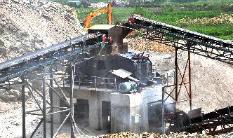
While teaching myself AutoCAD PID over the summer break I ran into some issues with inline blocks and database access. This is just a quick tutorial covering how to import a symbol/block into AutoCAD PID's database and access functions like scaling on insert, inline symbols/blocks (Join type), auto block nozzles and general style properties.
الحصول على السعر
Simply choose the PID template that is most similar to your project, and customize it to suit your needs. Exhaustive Engineering Symbol Library SmartDraw includes an extensive collection of mechanical engineering symbols and industrial templates for piping, instrumentation, HVAC, welding, ducts, tools machines, and more.
الحصول على السعر
Technical Standard TS 112 Process and Instrumentation Diagrams (PID) Revision: ... Custom symbol or code 4 PID Requirements Introduction A PID shows information on piping, fittings, equipment, instrumentation, and process plant in a ... a master legend for the set of drawings.
الحصول على السعر
the PID) Most industries have standardized the symbols according to the ISA Standard Instrumentation Symbol Specification. Piping and Instrumentation Diagrams or simply PIDs are the "schematics" used in the field of instrumentation and control (Automation) The PID is used to by field techs, engineers, and operators to better
الحصول على السعر
note: some symbols shown on this legend may not pertain to this project. symbol description symbol description symbol description f f h f c e fs ts f rt r r f ddc vfd c st ss gnd g cii ci f eq l c j a 2 electrical symbol legend general notes: dn thruroof conductor flat roof mounted or mechanical f p parapet mounted air terminal counterpoise ...
الحصول على السعر
Although the PID symbols are normally in accordance 2) During the project estimate, all equipment is shown, with ISA standards, it is recommended that a PID symbol but without auxiliary services such as cooling water key sheet be prepared with a summary of all equipment and to machinery.
الحصول على السعرCopyright ©2000-2023 TPCrusher CO.,LTD. خريطة الموقع
 WhatsApp24 ساعة عبر الإنترنت
 المحادثة على الإنترنت 24 ساعة عبر الإنترنت